
Annotation Capabilities With VTK 5.10

At the Direction des Applications Militaires Île-de-France (DIF) of the Commissariat à l’Energie Atomique (CEA), France, an application-specific visualization tool has been developed to post-process the solutions to the numerical simulations calculated at CEA/DIF. On the visualisation side, this tool uses VTK and ParaView servers.
Goals of the collaboration focused on adding new annotation capabilities to VTK, specifically in the areas of extension of the existing axis actor and cube axes actor; addition of a new polar axes actor; and improvement and enhancement of the scalar bar actor.
New mesh manipulation capabilities have also been added, including element selection along a line or a broken line; broken line widget for interactive element selection with a mesh; and quadrangle-generating mesh extrusion from a multi-block polygonal input.
This article will briefly report on these new capabilities, all of which are available in VTK 5.10 (see recent releases).
Cube Axes
Over the past few years, the 3D cartesian axis capabilities available with VisIt have been extended in order to introduce new capabilities; in particular, the ability to display internal grid lines and / or translucent cut planes within cube axes actors. In addition, about 30 control parameters regarding bounds, titles, colors, and labels were added to the original classes, as well as a specific 2D mode to handle poor title/label appearance for two-dimensional results. We integrated these changes to the VisIt classes into VTK, attempting to retain the pre-5.10 VTK behavior by default whenever possible.
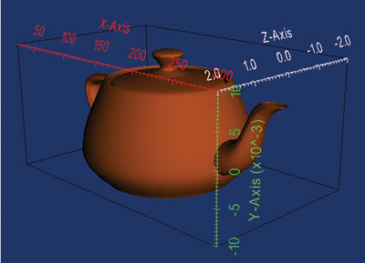
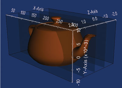
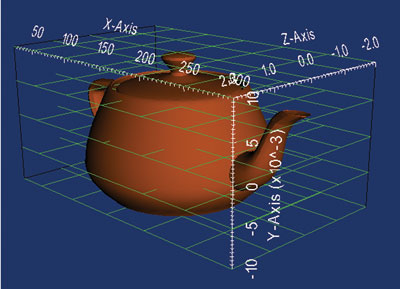
Figure 1: Use of Translucent Inner Planes and Inner / Outer Grids for Cube Axes Annotation
As illustrated in Figure 1, it is now possible to annotate cube axes with translucent inner planes and inner/outer grids. It is also possible to independently control settings for each axis including: axes bounds, text and color of each title, text and color of each axis and its labels, color and display of inner and outer grid lines; and color, translucency, and display of internal planes.
Polar Axes
In the context of this collaboration, we created a polar axes actor, a feature which did not exist in VTK until 5.10. The main goal of this actor is to allow for the display of a variable number of radial axes, with respect to user-specified origin and polar angle, along with polar arcs attached to the radial tick marks. We developed this new actor from scratch, based on CEA specifications.

Figure 2: Multiple Parameters of the Polar Axes
As illustrated here, a number of parameters of the polar axes can be independently tuned, such as origin and polar angle; number of ticks and polar arcs (or auto-calculation option); number, display, color, and length of radial axes; number, display, and color of polar arcs; text attributes of axes and arcs titles and labels; and level-of-detail parameters.
Scalar Bar
The class vtkScalarBarActor in VTK had been extended at CEA into a new class called vtkCEAScalarBarActor, in order to 1) modify the title and label placement within the scalar bar actor, in order to ensure that all text be placed within the interior of the specified 2D actor size, and 2) the addition of optional frame and background color, possibly translucent.
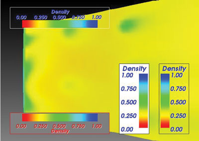
Figure 3: Scalar bar actor in VTK
As shown here, we ported these new features into the current VTK scalar bar actor. As a result, we had to modify its default behavior as it was not ensuring that all text remained within the frame, which led to visual defects when this option was added. We also used this opportunity to fix title placement behavior, which was exhibiting collisions with the color bar when placing letters such as ‘q’ or ‘y’. We implemented these changes for both horizontal and vertical bar layout.
Mesh Selection and Extrusion Capabilities
Linear Selector
A class for the selection of cells along a segment defined by its endpoints, within a composite dataset, had been developed at CEA/DIF. As part of our collaboration, we developed a new subclass of vtkSelectionAlgorithm, called vtkLinearSelector, which extends the method to support selection along broken lines within an input composite dataset. In particular, the API of this new selection algorithm allows for two different ways of defining a broken line: either by passing a list of vtkPoints, or by only specifying two endpoints in order to preserve backwards-compatibility for the CEA/DIF visualization application.
In addition, we enhanced the original method by allowing for the exclusion of line endpoints in the selection process; i.e., selection along open segments. We noticed with early experiments that typical use cases with CEA/DIF datasets were leading to numerous unwanted cells being selected in cases where a segment endpoint coincides (numerically) with a cell vertex within the input mesh. This exclusion method is based on an IncludeVertices option, which when turned off, makes use of a user-defined relative tolerance; thus defining a closed segment contained within, and numerically approaching, the actual open segment.
Incidentally, we discovered that the current implementation of the IntersectWithLine() method of vtkTriangle does not specifically handle the case of degenerate intersection; i.e., the (unstable) case where a segment is both coplanar and secant to a triangle. The current implementation works effectively as a dichotomy between either secant or coplanar, with the degenerate intersection belonging to the former case. This design is not faulty per se, for it was conceived as such for speed in the context of facet picking within a mesh. However, when using VTK in the context of topological/geometric manipulation, this becomes a problem as we discovered here. We initiated a discussion amongst VTK developers as to whether a modification of vtkTriangle::IntersectWithLine() is warranted in order to support the ternary division between generic intersection, non-intersecting coplanarity, and degenerate (co-planar) intersection. Due to the potential ramifications of such a change, we have decided to not not modify vtkTriangle::IntersectWithLine() until a consensus is reached in this regard. In the meantime however, this degeneracy does not cause any trouble for our CEA/DIF partners, for their visualisation application uses a version of vtkTriangle which they modified to handle this numerical issue in particular.
Broken Line Widget
Following the development of the broken line selection mechanism, we implemented a broken line widget to allow for interactive selection of cells within an input mesh. For consistency within VTK, we devised the API and behavior of the new vtkBrokenLineWidget to be similar to those of the vtkSplineWidget, so the developer already familiar with the latter will find it natural to use the former. In particular, mouse/button events produce the same results in terms of handle addition/deletion, panning, zooming, etc.

Figure 4: Broken Line Widget
The behavior of the new selection mechanism combined with broken line widget interaction can be interactively tested with the SegmentAndBrokenLineSources.py script, which we put under Examples/Graphichs/Python/ in VTK 5.10. It demonstrates the operation of the widget and lets the user interactively select cells within an example mesh, chosen for its peculiarity at the apex with multiple coincident pyramids, thus illustrating the use of endpoint elimination during the selection process.
Rotational Extrusion in Quadrangles
Among the modeling capabilities of VTK is the class called vtkRotationalExtrusionFilter, which takes polygonal data as input and sweeps it around the z-axis to create new polygonal primitives. These primitives form a “skirt” or swept surface. For example, sweeping a line results in a cylindrical shell, and sweeping a circle creates a torus. A number of control parameters are available: for instance, one can decide whether the skirt sweep of a 2D object (i.e., polygon or triangle strip) is to be capped with the generating geometry. It is also possible to control the angle of the rotation, and whether translation should be performed at the same time as rotation (screw action). The output skirt is generated by locating certain topological features: free edges (edges of polygons or triangle strips only used by one polygon or triangle strips), lines and polylines generate surfaces, whereas vertices generate lines.
This class, however, has the following limitations:
1. It can only generate triangle strips as output.
2. It can only sweep around the z-axis.
3. It does not allow native processing of multi-block inputs, with independent rotation angles specified for each block.
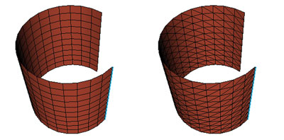
Figure 5: Rotational extrusion of a line parallel to the z-axis, in triangles (left) and quadrangles (right)
In order to address these limitations, a new class called vtkRotationalExtrusionFilter has been developed at CEA/DIF. In particular, the output of this new filter is a skirt made of quadrangles, as illustrated in Figure 5: left, the result of a rotational extrusion in triangles from a polyline containing 10 segments using vtkQuadExtrusionFilter; right, the output of vtkQuadRotationalExtrusionFilter applied to the same input, with the same parameters.
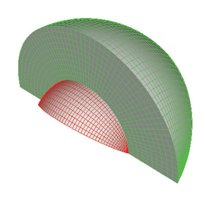
Figure 6: Rotational extrusion in quadrangles of a 2-block data set with a different angle for each block
As part of this collaboration with CEA/DIF, we ported the new class to VTK 5.10. We made a number of changes to make it easier to maintain and extend. In particular, we decided to keep it separate from vtkRotationalExtrusion, as opposed to merging the capabilities of both classes into a single new one; as illustrated above, vtkQuadRotationalExtrusionFilter is intrinsically a vtkMultiBlockDataSet algorithm, so we thought that for backwards-compatibility it was desirable to keep the triangle strip generating class as a vtkPolyDataAlgorithm, at least until a compelling reason to do otherwise would become manifest. The new, quadrangle-generating, multi-block filter is now fully-available with VTK 5.10, see Figure 6 above.
Acknowledgments
This work was made possible thanks to a contract with CEA, Direction des Applications Militaires Île-de-France (DIF), Bruyères-le-Châtel, 91297 Arpajon, France. We extend special thanks to Daniel Aguilera, Thierry Carrard, and Claire Guilbaud for this fruitful collaboration. We are looking forward to continued collaboration with CEA/DIF in this and other areas of scientific visualization.
 Philippe Pébay is the Director of Visualization and HPC of Kitware SAS, the European subsidiary of the Kitware group. Pébay is currently one of the most active developers of VTK, an open-source, freely available software system for 3D computer graphics, image processing, visualization, and data analysis. He is in particular the main architect
of the statistical analysis module of VTK and ParaView.