
Designing Nuclear Reactor Core Geometry and Meshes

Background
The computational analysis of complex physical systems, such as nuclear reactors, requires the ability to solve the behavior of several different physical phenomena (such as neutron transport, heat transfer, fluid flow, and thermal expansion) and to compute interactions among these physical phenomena. Essential to these analyses are the abilities to properly capture the geometric shape of the reactor and to assign information such as material properties and boundary conditions.
In addition, the analysis requires an “acceptable” computational mesh that conforms to the geometry, whose elements are of acceptable size and shape. Unfortunately, this is easier said than done for a high-fidelity reactor core simulation. A reactor core problem will involve more than a single component, and a reactor simulation is a multiphysics problem. This meshing workflow requires the coupling of various toolkits such as Meshkit from Argonne National Laboratory, Cubit from Sandia National Laboratory, and OpenCascade from OpenCascade SAS. Unfortunately, these tools are typically not integrated into a workflow that is intuitive for nuclear engineers, physicists, and experts to use.
In response to this need, we have developed an open-source GUI tool called the Reactor Geometry Generator (RGG) that is being funded by a DOE Nuclear Energy Fast Track SBIR. RGG also leverages work from some of Kitware’s existing projects including the Computational Model Builder (CMB), VTK, and ParaView.
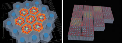
Examples of Nuclear Reactor Cores.
Nuclear Reactor Core Geometry
Nuclear reactor core geometry can often be described as having a two-level hierarchy of lattices; the first level of the hierarchy corresponds to fuel assemblies, formed as a lattice of cylindrical pins or compacts, while in the second level, assemblies of various types are arranged in a lattice to form the reactor core. These pins typically contain fuel, absorbing material for controlling the nuclear chain reaction, or instrumentation. The surrounding materials can function as coolant, as a neutron energy moderator, or simply as supporting structure. There are two common layout strategies used in the placement of pins within a reactor assembly or in the placement of assemblies within a reactor core. The first employs a rectangular lattice and is used primarily in water-cooled reactors. The other is a hexagonal-based approach mainly used in the design of sodium and gas-cooled reactors.
Reactor Core Meshing Workflow
The underlying workflow used in the RGG Application uses various tools to generate models and meshes of the reactor core including:
• AssyGen and CoreGen from MeshKit
• OpenCascade or ACIS Modeling Kernel toolkits
• Cubit
AssyGen takes in text files that describe subassemblies of pins and ducts, and it generates solid models of these assemblies. The assemblies are then passed to Cubit in order to generate hexahedral meshes of these assemblies. Finally, CoreGen takes these meshes, along with a core layout text file, to produce an acceptable mesh of the reactor core. Any modifications to the assemblies or core text files will require the appropriate sub-workflows to be re-executed. In addition, several key parameters such as size of the mesh elements along the outer boundary of the assemblies must match in order to generate an acceptable conforming core mesh.

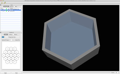
Simple hexagonal reactor core modeled in RGG.
Though this workflow is very powerful and can generate a large range of reactor core models and meshes, it is primarily targeted at computational scientists and meshing experts, rather than nuclear engineers. In addition, without the ability to visualize and graphically interact with key sections of the workflow, errors can occur, which may not be caught until the analysis itself is run, resulting in a waste of time and resources.
The Reactor Geometry Generator Tool
The RGG tool encapsulates the above workflow, allowing the user to see the different stages as well as the resulting core mesh. It guides the user through the process of designing pins, ducts, and assemblies, as well as the final core layout. It also allows the user to control the meshing process and prevents incompatible meshing parameters from being set.
Designing Pins
The first stage involves designing the individual pin cells that will be used in a reactor sub-assembly. As previously mentioned, these pins represent fuel, control rods, and various instrumentations. The pin cell editor presents a pin cell as a collection of segments. Each of these segments is shaped as either a cylinder or a truncated cone.

A pin being edited using RGG’s Pin Cell Editor.
A reactor assembly duct composed of 2 layers.
By default, the editor constrains neighboring segments to have the same mating radii. If the user changes one segment’s radius, all constrained radii are automatically updated. In addition, the pin editor allows the user to define contiguous layers throughout the pins. Each layer is assigned its own material.
Designing Assemblies
The next stage in the workflow is to design the sub-assemblies that will be used in laying out the core. Each assembly consists of a set of ducts that will contain the pins. Note that the overall height of the ducts and pins must be the same across all of the core assemblies. In order to enforce this, the user can set the overall core length, which is then enforced through the workflow. Similar to the pin editor, the GUI provides users with the ability to specify the duct structure of each sub-assembly. The following figure shows a simple duct being designed that consists of two materials. One material forms the walls of the sub-assembly, while water is assigned as the inside material.
Once the pins are designed, they are made available for placement with a sub-assembly lattice. The sub-assembly editor provides both a 3D view of the assembly and an editable 2D lattice view that supports drag and drop interaction. The offset between neighboring pins in the assembly is referred to as the pitch and is dependent on the size of the inner layer of the duct. Since the majority of assembly designs place the pins so that they are equidistant within the duct, RGG provides a mechanism to auto center the pins.
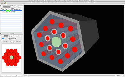
An example reactor assembly in RGG.
Laying Out the Core
In the next stage of the workflow, the complete core is defined by placing the different sub-assemblies into the core’s lattice. Similar to the sub-assembly editor, the core editor view provides a 3D view of the core, as well as the editable 2D lattice views. The figure below show various examples of core layouts.

Examples of different reactor core layouts using RGG.
Generating the Core Mesh
The final step of the process involves calling Assygn, CoreGen, and Cubit in order to produce the required solid models and meshes. The user can initiate this process through the RGG application itself. RGG does this through using the Remote Meshing Utilities (ReMUs), which is part of the open-source CMB effort. ReMUs can execute the various tools while allowing RGG to remain interactive. ReMUs relays the status of these external tools back to the user, while also providing the user with the ability to abort the sequence while it is running. Once the process is completed, RGG allows the user to display the core mesh, as well as visualize the various components of the mesh, based on volumes, materials, and boundary condition surfaces.

An example of a nuclear reactor core mesh generated using RGG.
In addition to guiding the user through the process of defining a reactor model, the application provides the user with a material library. The application can be easily extended to also provide pre-defined pin libraries.
Release
We anticipate the public release of version 1.0 of RGG in August 2014. The source code will also include a CMake SuperBuild for building MeshKit, which is also available as open source, as well as its dependencies, OpenCASCADE, VTK, and QT. The Cubit mesher is available through Sanida National Labs.
Acknowledgements
We would especially like to recognize Tim Tautges for his contribution to the project and Sandy McKenzie for her contribution to this article.
This material is based upon work supported by the Department of Energy under Award Number DE-SC0010119.
This report was prepared as an account of work sponsored by an agency of the United States Government. Neither the United States Government nor any agency thereof, nor any of their employees, makes any warranty, express or implied, or assumes any legal liability or responsibility for the accuracy, completeness, or usefulness of any information, apparatus, product, or process disclosed, or represents that its use would not infringe privately owned rights. Reference herein to any specific commercial product, process, or service by trade name, trademark, manufacturer, or otherwise does not necessarily constitute or imply its endorsement, recommendation, or favoring by the United States Government or any agency thereof. The views and opinions of authors expressed herein do not necessarily state or reflect those of the United States Government or any agency thereof.

Jacob “Juda” Becker is an R&D Engineer at Kitware, Inc. He has an M.S. in computer science from RPI. His main areas of interest are computer vision, machine learning/artificial intelligence, computational archaeology, and green technology.

Zach Mullen is an R&D Engineer at Kitware, Inc. His areas of interest include big data management and analysis, scientific visualization, quality software process, and computer security.

Yumin Yuan is an R&D Engineer on the Scientific Computing team at Kitware, Inc. He is the main software architect of the suite of CMB applications that regard geometric modeling, meshing, pre- and post-simulation analysis, and visualization.

Rajeev Jain is a Software Development Specialist at Argonne National Laboratory. He is a member of the American Nuclear Society. His research interests include software development, mesh generation, design optimization, and physics simulation.

Bob O’Bara is an Assistant Director of Scientific Computing at Kitware, Inc. His main areas of interest are geometric modeling, mesh generation, model and mesh visualization, and general scientific visualization techniques.

Patrick O’Leary is an Assistant Director of Scientific Computing at Kitware, Inc. He also leads Kitware’s office in Santa Fe, NM. His research interests include high performance computing (HPC), numerical analysis, finite elements and visualization.