
Finite Element Based Biomechanical Analysis of Cranial Shapes for Craniosynostosis Surgical Correction

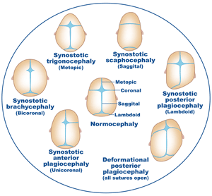
Craniosynostosis is a birth defect caused by the premature closing of one more sutures on a child’s head. This results in an abnormal skull shape that can potentially cause excessive intracranial pressure. There are different types of craniosynostosis with varying levels of severity (Figure 0). The only treatment for children with craniosynostosis is surgical cranioplasty (strip craniotomy).
Typically, the decision of performing surgical correction for patients with craniosynostosis is based on subjective visual assessment of the severity of the cranial malformation. Due to the invasiveness of the procedure, these decisions have a major impact on the management of the young patients requiring surgery.
The bone correction procedure can be simulated via biomechanical modeling based on the actual physical properties of the bone. The resulting shape and stress distributions of the bone can then be used to evaluate and compare individual bone correction plans before carrying out the actual surgery. For example, depending on bone rigidity, the cranial bone might fracture due to the increased amount of pressure during surgery. Therefore, stress measurements may help eliminate surgical plans that might result in undesirable bone fracture.
FEM Modeling
We use a finite element method to simulate the bending of the skull due to pressure forces. These pressure forces are the result of shape deformations from a malformed skull into a desired shape. The finite element method is a numerical method to approximately solve boundary value problem from partial differential equations that has it origins from the need to solve structural analysis problems in mechanics. Our main goal is to use finite element-based structural analysis and simulation to measure stresses on a cranium due to external pressure forces.
 a.
a. 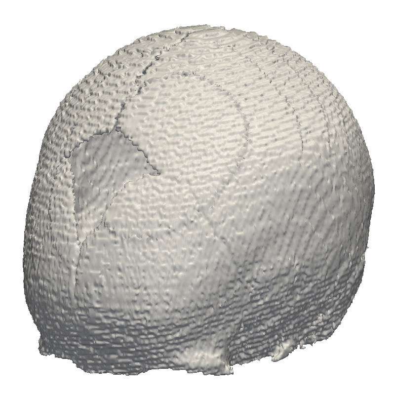 b.
b.
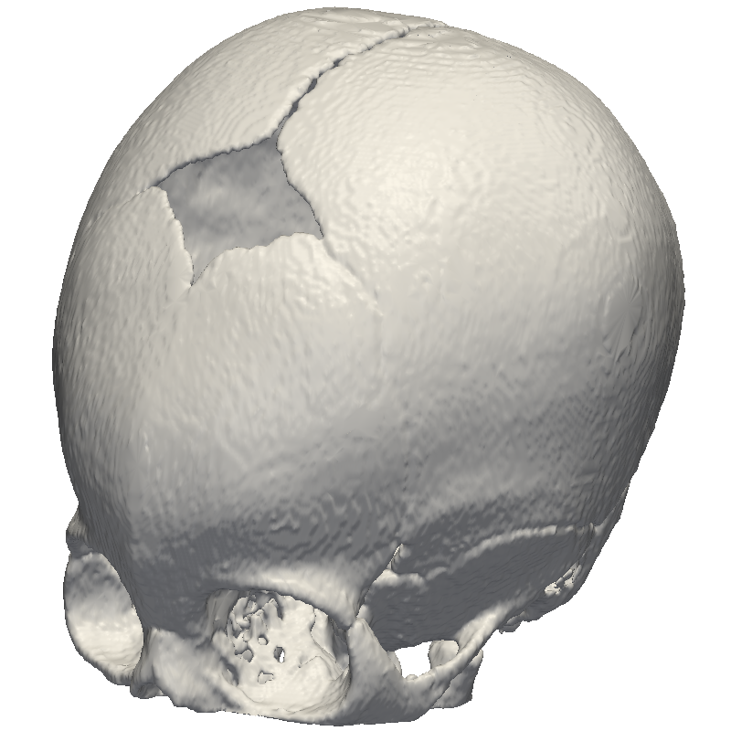
Two CT scans from a craniosynostotic pediatric patient were binarized to extract the skull and used to create the models: one of a malformed skull before surgery and the other of the desired post-correction shape (see Figure 1). A tetrahedral mesh is then generated for each label map and used as the input for the finite element method.
Boundary Conditions
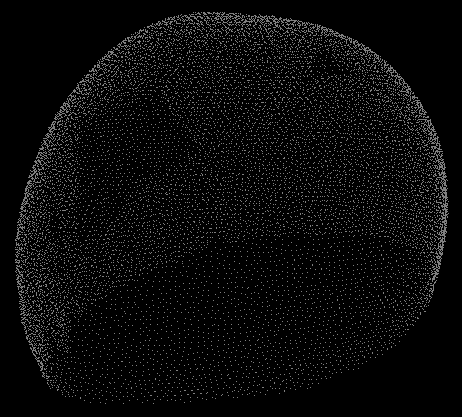
The main tasks of the effort are 1) to reshape the image in Figure 1a. into the image Figure in 1b and 2) compute stresses due to that reshape. In order to accomplish this, we need to specify the correct boundary conditions on the surface of the mesh. The boundary conditions are specified only on the outer surface of the skull as pressure field computed from a displacement field. This displacement field is generated from the displacements of points on mesh with deformity (Figure 1a) onto mesh in Figure 1b. This displacement field is computed by taking a subsampling of points on the surface of each mesh and finding a correspondence between the point clouds (see Figure 2). The correspondence is found by simply using a point locator on the first cloud (Figure 2a) and averaging the vector differences of a fixed number of neighboring points from the other cloud (Figure 2b).
 a.
a. 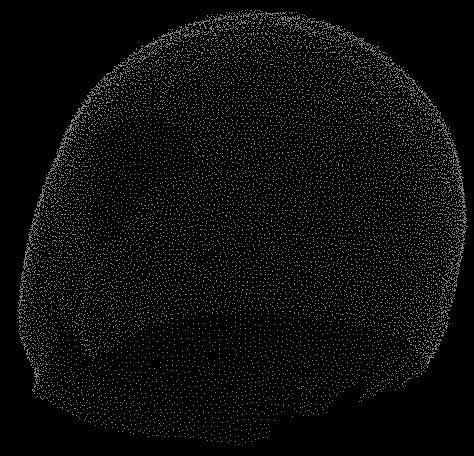 b.
b.
Figure 2. Point clouds of mesh top surface for a) deformed shape and b) desired shape.
This resulted in a vector field that maps a subset of points from one cloud to another (see Figure 3). This vector field is used to apply the pressure force boundary condition on the surface of the mesh of the craniosynostotic skull in order to make it “bend” in the direction of the desired shape.
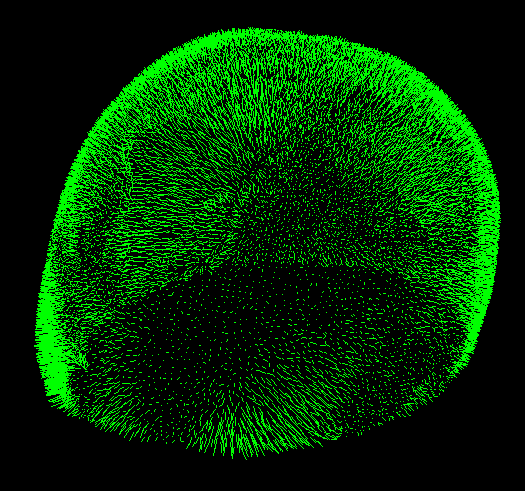
Figure 3. Displacement field computed from point clouds.
Slicer Module
We developed a Slicer module using Bender-SOFA interface (see Figure 4). The module IO tab takes the two point clouds and the craniosynostotic mesh and uses this data to compute the displacement field. The module Simulation tab takes general parameters for the simulator and material properties for the mesh. Optionally, you can load SOFA’s GUI if you want to keep track of the simulation.
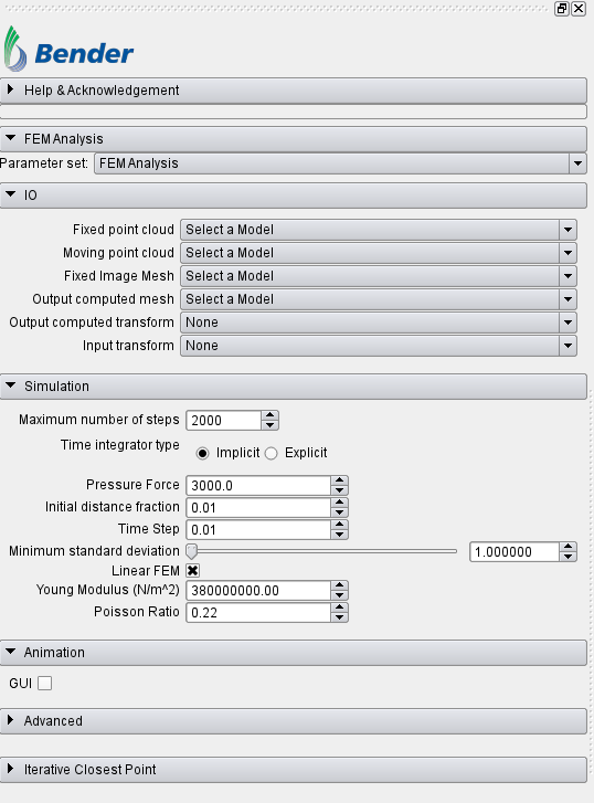
Figure 4. Slicer module GUI.
Results
Results are shown in Figure 5. The intensity of the displacement can be seen more pronounced on those areas around the forehead, topping at about 4mm where the biggest deformation is happening with a corresponding stress distribution of about 30MPa.
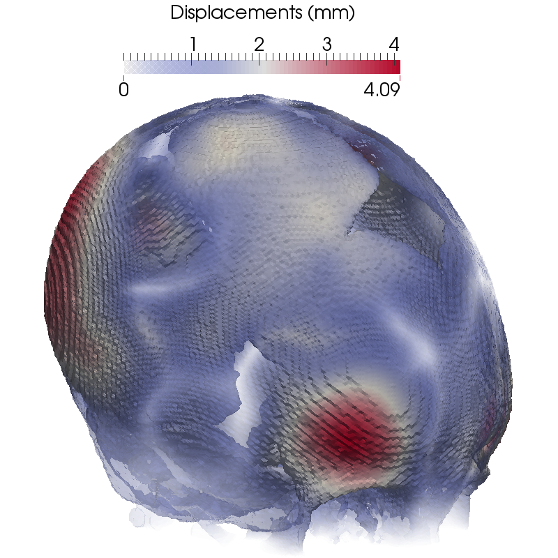

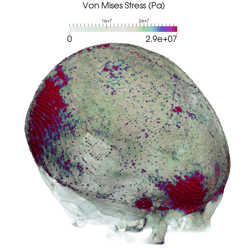
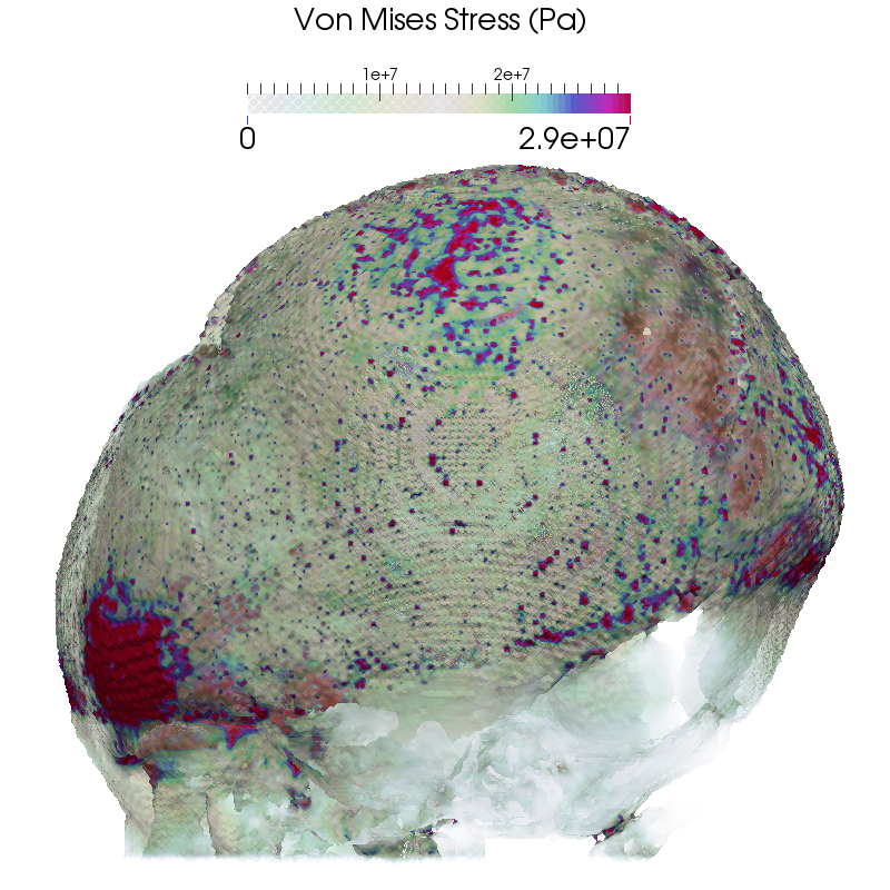
Figure 5: Computed displacement fields (Top) and Von Mises stress distribution (Bottom) in two orientations.
Note that the computed stresses for this craniosynostotic patient are significantly lower than the maximum allowable stress of 87MPa.
ACKNOWLEDGMENT: Research reported in this publication was supported by the Eunice Kennedy Shriver National Institute Of Child Health & Human Development of the National Institutes of Health under Award Number R41HD081712. The content is solely the responsibility of the authors and does not necessarily represent the official views of the National Institutes of Health.