Physically Based Rendering improvements in ParaView
Introduction
The Physically Based Rendering shader in VTK has recently been improved with the addition of an anisotropy and a clear coat model. We are very glad to announce that these improvements are now merged in the latest ParaView master and will be available in few months in the 5.10 release !
With the recent additions of Image Based Lighting with High Dynamic Range (HDR) images paired with Tone Mapping and Screen Space Ambient Occlusion in ParaView, the rendering in ParaView enters a new dimension of realism that will allow users to put their visualizations in the real world.
Usage
The new parameters for the Physically Based Rendering interpolation mode under the Lighting property group are depicted in Figure 2 below. Theses parameters allow you to add a tint to a metallic material edge, to create anisotropic materials, or to add a layer of coating on top of your object.
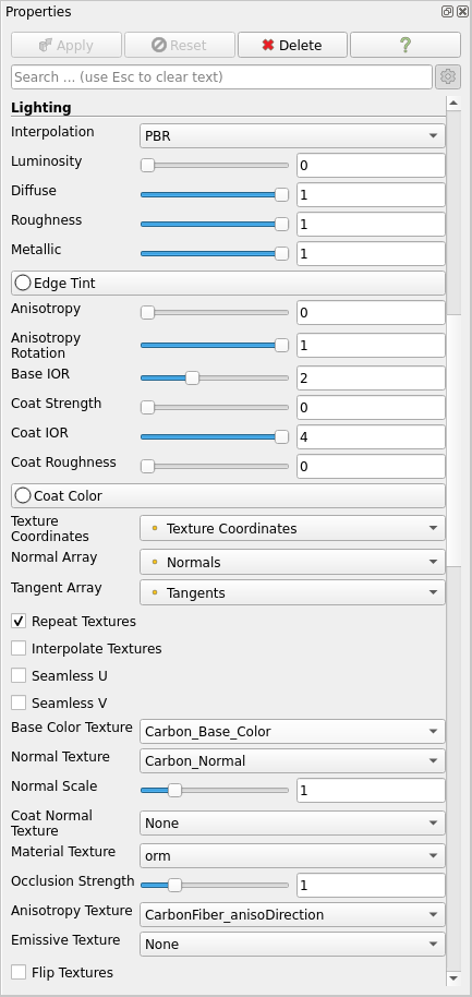
Edge Tint
This property works only on metallic materials and adds a color at the edges of the material.
Anisotropy
Anisotropic materials have different reflecting properties that depend on the direction of the anisotropy, which is defined by the tangent of the geometry and its rotation. The more anisotropic a material is, the more its lighting is influenced by its direction. Thus, it is necessary to have normals and tangents in order to have an anisotropic material.
Two parameters allow the control of a material’s anisotropy :
- Anisotropy : The strength of the anisotropy (between 0.0 and 1.0). 0.0 means an isotropic material, 1.0 means a fully anisotropic material.
- Anisotropy Rotation : Rotates the direction of the anisotropy (ie. the tangent) around the normal counter-clockwise (between 0.0 and 1.0). A value of 1.0 corresponds to a rotation of 2 * PI.
In order to render more complex anisotropic materials, you can load an anisotropy texture that will hold the Anisotropy Strength in the red channel, and the Anisotropy Rotation in the green channel (blue channel is discarded). Texture examples can be found in this blog.
Clear Coat Layer
A coat layer can be added to reproduce coating such as paint on top of the base layer. This layer is isotropic and its interaction with the base layer can be configured with various parameters :
- Base IOR : This property controls the Index Of Refraction of the base layer. The more the IOR goes up, the more light will be reflected on the base layer.
- Coat Strength : This property allows you to enable / disable the coat layer. Values between 0.0 and 1.0 can be considered as the thickness of the coating (even if values between 0.0 and 1.0 are not entirely physically based).
- Coat IOR : This property controls the Index Of Refraction of the coat layer. The more the IOR goes up, the more light will be reflected on the coat layer before being transmitted to the base layer.
- Coat Roughness: Controls the roughness of the coat layer.
- Coat Color : Controls the color of the coating. Specular reflections on the coat layer are always white, but this parameter modifies the radiance that passes through it.
- Coat Normal Texture : This texture can be loaded to use normal mapping for the coat layer. Ensure that texture coordinates and tangents are defined in the geometry as it is needed to do the normal mapping.
Current limitations
Currently, due to issue #20657, ParaView fails to send the tangents to the server when using :
- Local rendering in Client / Server mode
- Local and Remote rendering in Client / Render Server / Data Server mode.
This means that you cannot currently construct anisotropic materials nor use normal mapping if you are in one of these configurations. We hope this issue will be fixed soon.
Acknowledgements
This work is part of an innovative effort by the Scientific Visualization team at Kitware Europe and was partly funded by the VESTEC project.

The VESTEC project has received funding from the European Union’s Horizon 2020 Programme for research, technological development and demonstration under grant agreement no 800904.
It is possible to combine ray tracing with “cull frontface” as it seems it’s not working?