ParaView Aids In Silico Modeling and Visualization for Fracture Fixation in Osteoporotic Bone
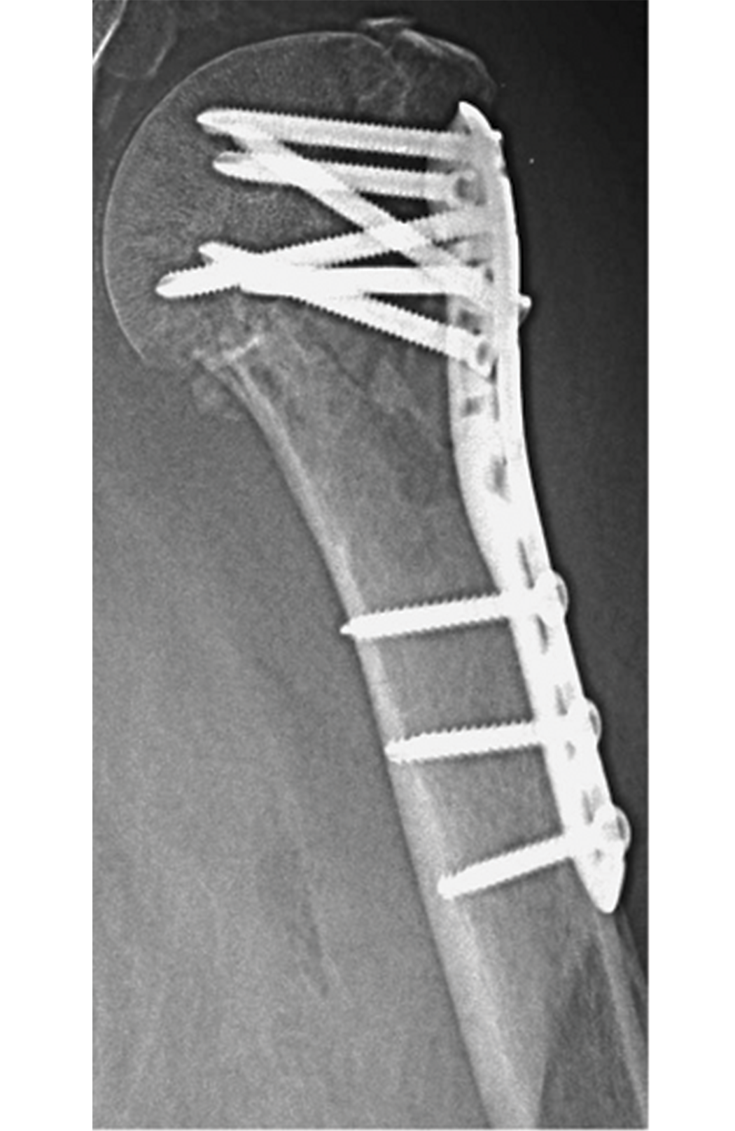
Steiner et al. note that osteoporosis has become more common in today’s aging population [1]. Treating fractures in patients with osteoporosis has also become more difficult, as implants such as titanium screws and plates impair the microstructural quality of bones [1]. The image below provides an example.
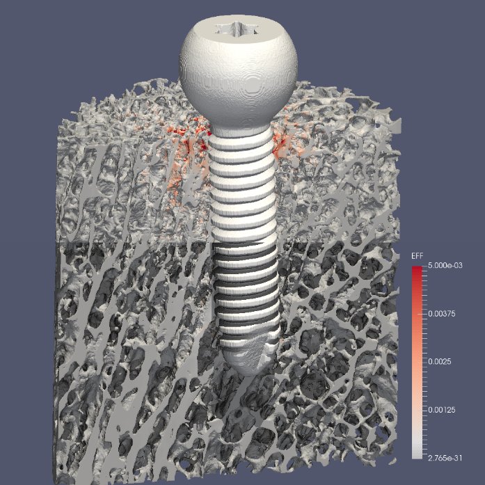
According to Steiner et al., in vitro biomechanical tests can examine the mechanical efficacy of implants, but they come with significant costs [1]. Computational specimen-specific models, however, allow a single bone specimen to undergo multiple mechanical tests [1]. Steiner et al. use micro-computed tomography (micro-CT) based finite element (µFE) analysis, which tests bone-screw models in silico [1]. This analysis employs micro-CT to scan a specimen at a nominal isotropic resolution of 20 µm [1].
The image below offers an example.
The ParaSol solver is used for these µFE models and runs on the leading Cray supercomputers at the Swiss National Supercomputing Centre (CSCS). Models typically range in size from 50 to 500 million hexahedral cells, and they pair well with the state-of-the-art data processing and analysis algorithms and the advanced rendering methods in ParaView. This article describes the current state of the implementation of ParaView at CSCS, which has grown over the last few years.
Parallel Reading
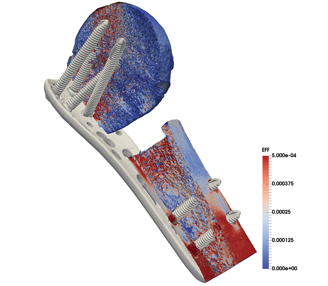
ParaSol stores the models in Hierarchical Data Format 5 (HDF5) as a single mesh of hexahedral elements. The software encodes materials (e.g., bones, screws, and plates) as an unsorted element-based variable. ParaView reads data in parallel due to the sheer size of the data. The size of the model shown above (414 million hexahedra) requires the use of 32 Cray nodes with 32 GB of memory. Each node allocates four Message Passing Interface (MPI) tasks for an average of three to five million cells per task.
ParaSol stores the mesh data in a sequence order that corresponds to the scanning device. To promote the use of large block input/output and to read consecutive node numbers, the CSCS team reads data by chunks. ParaView spreads the total number of cells among pvserver tasks, renumbers the nodes, sorts the material locally, and performs MPI gather/broadcast operations to enumerate the number of materials.
Surface Extraction, Ghost Cell Generation, and Visualization
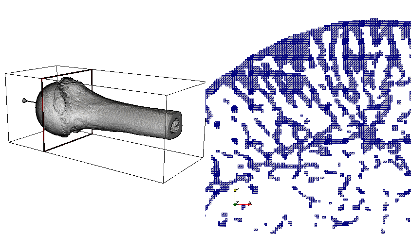
The very porous nature of human bones exacerbates the visualization challenge. A slice through a bone sample readily illustrates the challenge in the image below. Computing an external surface mesh results in unusually high triangle and vertex counts, as many bone filaments make up the whole structure. The specimen shown below has 92 million hexahedra, 10 million vertices, and an external surface of 34 million triangles—a reduction factor of barely one third! The recent move to OpenGL2 rendering and the improved edge rendering with Fast Approximate Anti-Aliasing (FXAA) in ParaView have increased rendering speed for these very large surfaces.
Yet, the hexahedral mesh (a by-product of the ortho-normal computerized axial tomography scan device) does not have a smooth external surface. While ParaView provides a Smooth filter, ghost cells must be created at processor boundaries to ensure the continuity of the surface. In previous versions of ParaView, the D3 filter evenly divided data across processors into spatially contiguous regions with a K-dimensional tree. This resulted in massive data migration from the natural mono-axis cell ordering that originated from the scanning device, as the right-hand portion of the image below illustrates.
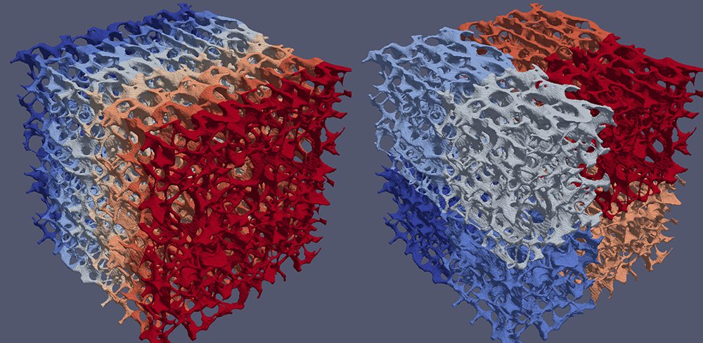
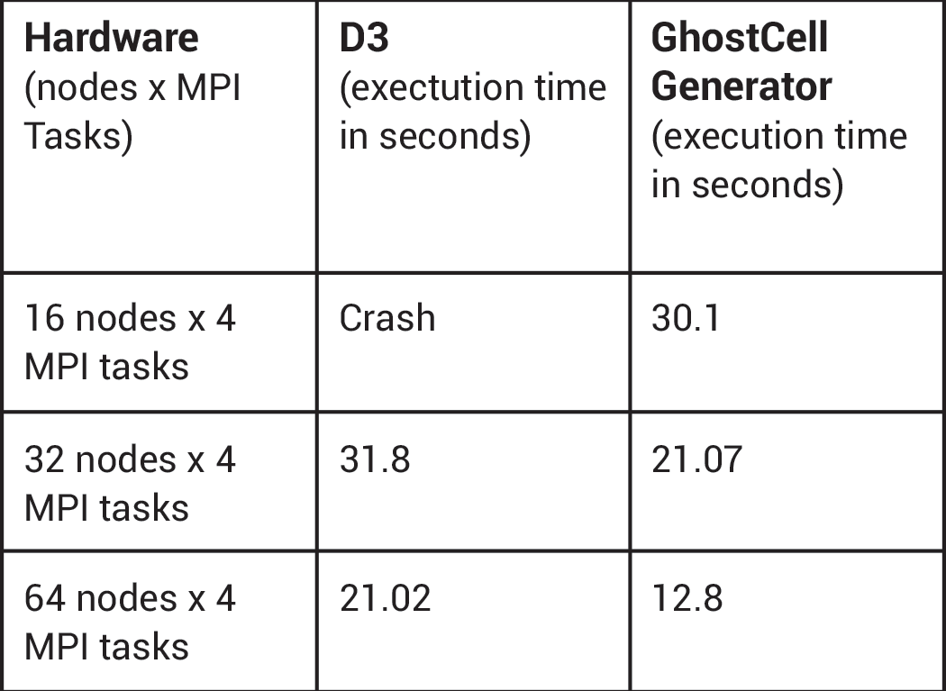
GhostCellGenerator (left) and D3 (right) perform processor coloring.The team at CSCS spontaneously adopted the GhostCellGenerator filter, which the ParaView development community introduced in 2016 [2]. This filter does not redistribute the input data; it only generates ghost cells at processor boundaries. To do so, it fetches the topological and geometrical information of those cells on neighbor ranks. The filter can benefit from global point IDs, which a plug-in created by the CSCS team provides. The team tested D3 and GhostCellGenerator with an input mesh of 285 million hexahedra. GhostCellGenerator proved much better both in memory consumption and in performance, as the table below indicates.
Real-time Ray Tracing
The intricate and complex internal surface of bones requires advanced rendering. The image below illustrates this fact unequivocally. A new rendering capability in ParaView augments dull renderings of the past—see the top of the bone sample—with shadows and takes into account the reduced visibility of pixels deeper within the bone structure. OSPRay, the open-source interactive ray-tracing library from Intel®, provides this new capability and enables real-time rendering of large models at CSCS [3].
Summary
ParaView has made a tremendous contribution to the visualization needs of CSCS. From distributed mesh management with ghost cell generation to advanced rendering, the implementation of ParaView has greatly contributed to the analysis of in silico fracture fixation implants in osteoporotic bones at CSCS.
References
[1] Steiner, Juri, Harry Van Lenthe, Stephen J. Ferguson, and Jean M. Favre. “In-silico Modeling for Fracture Fixation in Osteoporotic Bone.” In Proceedings of the International Conference on High Performance Computing, Networking, Storage and Analysis, 89. Proceedings of SC13, Colorado, Denver. Institute of Electrical and Electronics Engineers, 2013. http://ieeexplore.ieee.org/xpl/mostRecentIssue.jsp?punumber=6869133.
[2] Quammen, Cory, Utkarsh Ayachit, Andy Bauer, David DeMarle, Sujin Philip, David Lonie, and Ken Martin. “ParaView 5.2.0 Release Notes.” Kitware Blog, November 15, 2016. https://blog.kitware.com/paraview-5-2-0-release-notes.
[3] DeMarle, David. “VTK and ParaView – now with ray traced surface rendering.” Kitware Blog, May 11, 2016. https://blog.kitware.com/vtk-and-paraview-now-with-ray-traced-rendering.
 Jean M. Favre is the visualization task leader at CSCS in Lugano, Switzerland. His interests focus on high-performance computing and visualization.
 Juri Steiner recently completed his doctoral thesis at Eidgenössische Technische Hochschule Zürich on the validation of patient-specific computer models that simulate the mechanical behavior of fracture fixation implants in osteoporotic human bone. His interests include high-resolution computed tomography, patient-specific finite element analysis, and biomechanical experiments.